Project Information
Name:
The Ridges
Broomfield, CO
Product: AB Classic
Size: 17,265 ft2 (1600 m2)
Wall Builder:
Slaton Bros.
Centennial, CO
Wall Designer:
SK Designs
Lakewood, CO
Allan Block Manufacturer:
Basalite, Denver, CO
Detail 4
Global Stability Analysis Saves the Day
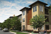
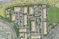
The Ridge at Broomfield is a 15-acre, new multi-family development located in Broomfield, CO – just outside of Boulder. Broomfield has recently experienced a multi-family boom and when completed, the project will include 292 rental units in the sought-after neighborhood. The reasons for the boom are plentiful and include easy access to I-36, proximity to public transit, recreation, employment and downtown Boulder. With one, two and three-bedroom rental properties, The Ridge at Broomfield will provide many individuals and families with a fun environment and a great home for years to come.
Plan:
Embrey Partners, the owner of The Ridge at Broomfield put together a strong design team to create the multi-family facility. Maximizing buildable land was critical on this parcel, but various conditions onsite would create challenges for the future development. Harris Kocher Smith, the Civil Engineer for the project, created a site plan to offset significant grade changes and slopes to fulfill Embry Partners’ needs by incorporating segmental retaining walls. The preference was to create the shortest retaining walls possible to offset the topography challenges. The finished plans included:
- Wall heights up to 12 ft (3.6 m)
- 4:1 slopes above (extending away from the wall nearly 100 ft (30 m)
- 4:1 slopes below the wall (extending away from the wall nearly 40 ft (12 m) in areas)
- Soil with a friction angle of 22 degrees
- Water issues from behind the wall
- High ground water resulting in water issues within the base
This type of topography, water concerns and poor soils are common in the local market and fortunately, the design professionals were prepared to handle the obstacles due to their experience with such conditions. Proper planning led to efficient execution in the field.
Detail 2
Detail 1
Design:
SK Design in Lakewood, CO was hired as the retaining wall design professional. The slopes, poor soils and high-water table were SK Designs top concerns. While 4:1 slopes by themselves are not severe, when combined with the other site conditions, a global stability analysis was used to control the design. Global stability is defined as the ability of a system to withstand great disturbances without being greatly affected. Relating to the retaining walls onsite, SK Design had to ensure the stability of the numerous hillsides due to the additional weight of each retaining wall. By reviewing the site conditions and performing all the required engineering analysis, it was determined that the Allan Block Classic product would be the perfect option for the retaining walls on site. The flexibility of the Allan Block system allowed SK Design to develop a design to correct the many site challenges.
As read in Best Practices for Segmental Retaining Wall Design, typical grid depth for a segmental retaining wall is equivalent to 60% of the overall wall height, block embedment is typically 1 in. (25 mm) per every 1 ft. (0.3 m) in wall height (6 in. (150 mm) minimum) and the wall leveling/foundation pad is typically 6 in. (150 mm) thick and twice the depth of the wall unit (most often 24 in. (610 mm)). To compensate for global concerns and water table challenges, SK Design had to deviate from these “standards” and incorporate additional details to ensure the walls would last a lifetime.
Detail 3
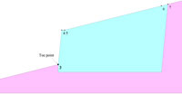
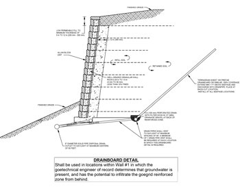
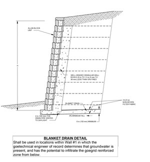
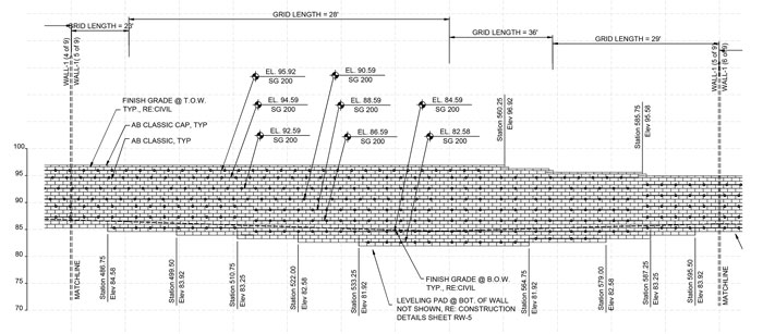
As seen in Details 1-4, the flexibility of the Allan Block system and AB Walls 15 Design Software allowed SK Design to use their expertise to efficiently create a design tailored to The Ridge at Broomfield. Detail 1 and 2 show water management practices such as blanket and chimney drains to help remove water from behind and below the application.
The blanket drain used to help remove water also incorporated a french drain. French drains are common solutions when water is present within the base. The chimney drain was a manufactured drainboard to help remove water from behind the structure as seen in Detail 2. Both the blanket and chimney features were incorporated to help reduce the likelihood of hydrostatic pressure building within the reinforcement zone. Detail 3 and 4 will provide a visual of what may happen when global stability is a concern. Instead of grid depths in line with Best Practices, walls on The Ridge at Broomfield site saw grid extended to 200-300% of wall height in worst case scenarios. You will also notice the additional depth needed to compensate for the toe slope in Detail 4. For a 12 ft (3.6 m) tall wall there is over 2.5 ft (0.75 m) of block buried which is much more than typical Best Practices standards previously discussed. Steve Kelley with SK Design was excited about the opportunity to design such a project and recently shared with us “the design challenged me to use a variety of details and pull from a variety of experiences to safely satisfy the requirements of the site and to ensure once built, the wall would last a lifetime.”
Build:
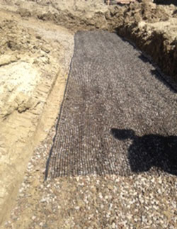
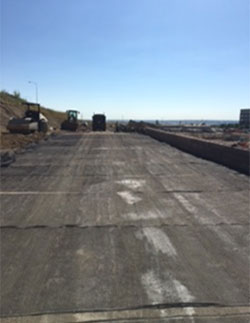
Slaton Brothers, of Denver CO, (has several Allan Block Master Wall Builders on staff) were retained as the wall installer. Their experience, training and attention to detail was imperative to the long-term success of the project due to the various site challenges previously outlined. This design was unlike most they see and during construction they had to pay close attention to the design details. In addition to the french drains outlined above, they also had to install reinforcement within the retaining wall foundation for added stability. Their expertise was put on display when installing the manufactured chimney drain as well. Since they could not cut vertically due to the wall height and OSHA requirements, the chimney drain had to be installed on a 45-degree angle and precisely done to allow for collection of water from behind the reinforced mass. Slaton’s performance was superb, and the meticulous details outlined within the design were easily incorporated within the Allan Block structure to overcome the hazards of this treacherous site.
