Complex Composite Structures (CCS)
Complex Composite Structures will be defined as walls that the engineer needs to evaluate as a single wall section with two distinctly different structures positioned one on top of the other. Engineers are often faced with situations that simply do not fit into the straight forward scenarios found in published design methods for SRW projects. The following provides a path to analyze more complicated applications that we will refer to as Complex Composite Structures (CCS).
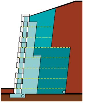
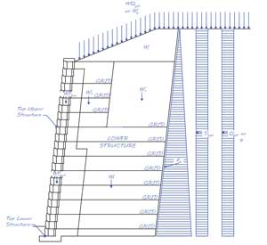
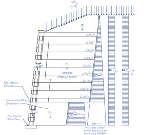
Figure 7.1 Complex Composite Structures (CCS)
These are identified as complex because they are structures that are a combination of more than one uniform structure. They are composite structures because they rely on multiple materials to resist driving forces to create a safe and effective retaining wall solutions. Typical current design approaches incorporate a similar method when they calculate the top of wall stability for the gravity wall above the top layer of geogrid. This analysis will be presented in a working stress design approach, but could easily be adapted to a limit states approach. Currently we have found that lacking any clear direction to evaluating these types of structures, engineers are faced with having to use their best judgement to create a reasonable analysis for their unique application. This approach provides a more refined method to ensure your design meets the performance standards expected.
Listed at the end, are the various wall configuration examples that can be analyzed in AB Walls Design Software as Complex Composite Structures and a set of hand calculations explaining the design process. The design premise will be to design the Upper Structure as a separate wall from the Lower Structure and the Lower Structure as a separate wall with the Upper Structure applied as a surcharge. The complex structures will not be set up to calculate a terraced arrangement. In other words, the facing will be continuously stacked from bottom to top.
The two separate wall calculations will focus on External Stability and to evaluate Internal Compound Stability (ICS) in place of typical internal calculations. The ICS calculations provide a more refined analysis on the internal stresses and resisting forces at multiple slip arc locations. In keeping with the HCMA approach, a design envelope equal to the greater of, twice the height of the total wall structure (2H), or the effective height (as determined by the height intersecting the slope at the back of the reinforcement) plus the length of the primary geogrid (He + L) will be used to define the limits of where the ICS will be conducted. The ICS calculations will be run on the total height of the Complex Composite Structure and not specifically on the two elements that make up the CCS. Running ICS for a CCS does not in any way replace the need to have a global analysis conducted to ensure the overall site stability is achieved.
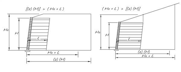
Figure 7.2 ICS Design Envelope Diagram
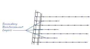
Figure 7.3 Secondary Reinforcement Layers
This also provides a future path to evaluating secondary reinforcement, as the concept of secondary reinforcement for facial stability is developed by the industry. Slip arcs used to evaluate internal loads and resisting forces will be constructed using a Modified Bishops approach as used in typical geotechnical slope stability analysis. Contribution from the facing will follow the methods outlined in the Allan Block Engineering Manual which employs shear and connection to quantify these resisting forces.
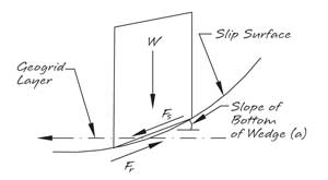
Figure 7.4 Modified Bishops Method
On any structure where more than one layer of reinforcement is shorter than the lengths of the other reinforcement, at the top of the wall, the CCS method will be utilized. For applications where obstructions occur at the bottom portion of the wall structure we do not recommend shortening the grids at the bottom, but we provide the engineer the ability to use no-fines concrete for the Lower Structure. The CCS analysis will provide the engineer the ability to review the suitability of the resisting forces of two different structures, as independent masses, and working together to resist forces that are being applied from the same retained soil mass and all external forces.
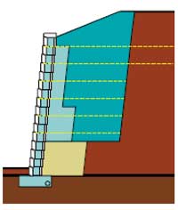
Figure 7.6 Grid Above No-Fines CCS
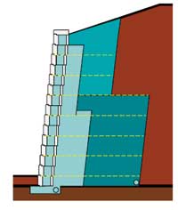
Figure 7.5 Grid Above Grid CCS
The Upper Structure of the CCS will be examined from an External Stability standpoint twice. First the entire top wall will be analyzed by calculating the driving forces, static and dynamic, and comparing it to the resisting forces based on the configuration of the Upper Structure’s mass. Additionally, a gravity wall analysis will be run for those unreinforced courses above either the top layer of geogrid or above the no-fines mass when used. For an expanded discussion on this topic see the Top of Wall Stability section. This will ensure that localized toppling does not occur. Please remember that the internal analysis is now being conducted using ICS. This which will ensure that the elements that the Upper or Lower Structures are comprised of will hold together as a composite mass.
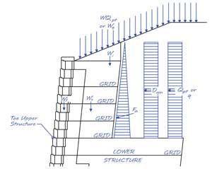
Figure 7.7 Upper Structure Force Diagram
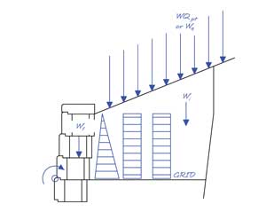
Figure 7.8 Top of Wall Stability Diagram
Conducting an External Stability Analysis
There are many combinations for how the project application may require various structural configurations to be designed and assembled to create a CCS. On any given structure there may be three separate External Stability calculations: Lower Structure, Upper Structure, and a gravity wall check above the last layer of reinforcement or above the no-fines mass. The External Stability of the top of wall section and the Upper Structure of a CCS will be calculated as a gravity wall using its own height and depth variables (block, block plus no-fines, block plus geogrid). The Upper Structure can be a reinforced soil structure with shorter geogrid lengths than the Lower Structure, a no-fines concrete mass, a single or double block wall, or a short or long anchoring unit walls. Sliding will be calculated as usual with the addition of the shear lip values at the intersection of the Upper and Lower Structure. The shear capacity is determined though testing (ASTM D6916) and increases linearly based on normal load above the tested course.
The Lower Structure can be a geogrid reinforced mass (provided that the grid lengths of the Lower Structure are equal to at least 60 percent of the height of the total structure), or a no-fines concrete mass. The Lower Structure will be calculated with the Upper Structure as an applied surcharge. For the overturning calculations, a set of moment arms will be developed to accurately define each possible soil type and weight above as we develop a conservative approach to the more complicated CCS configuration. The active earth pressure will be calculated for the full height of the structure.
External Stability where the Upper Structure extends beyond the Lower Structure
When the Upper Structure extends beyond the depth of the Lower Structure an additional investigation of bearing capacity will be performed on the soil mass behind the lower wall. A limiting ratio of top wall to bottom wall depth of 70% has been implemented based on reviewing outputs and establishing practical limits to a CCS. Therefore if the Upper Structure is 10 ft (3 m) deep measured from the face of the wall to the back limits of the mass, the Lower Structure can be no shorter than 7 ft (2.1 m). These additional calculations are designed to eliminate buckling at the intersection of the Upper and Lower Structure.
The active earth pressure for the Lower Structure will be calculated based on the full height of the total structure, at the back of the deepest structure. To add a level of conservativeness, the moment arms for the active earth pressure for the loading for the Lower Structure will be applied at the back of this shorter lower mass.
Having the Lower Structure shorter in depth to the Upper Structure raises questions about overall wall stability. As mentioned above, the current version of AB Walls will consider soil bearing behind the lower mass. From a bearing standpoint we will use our industry common Meyerhof method, distributed over the bearing width of Lwidth = SDtop – SDbottom. By calculating all the applied weights and forces we can use the typical Meyerhof equations, see sample calculations.

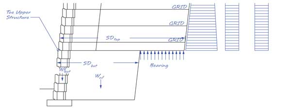
Figure 7.11 Bearing Behind Lower Structure
In this equation, Ldepth is the depth of leveling pad which will be zero in this case since we are not providing one and D is the depth of buried block. One can justify using Htop (the height of the top structure) as the depth of buried block, however, Meyerof’s equation reacts very favorably to additional buried block therefore we will limit this term to be equal to ½ Htop to be conservative.
Internal Analysis Performed using an Internal Compound Stability (ICS) Analysis
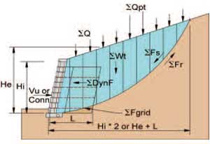
Figure 7.12 ICS Design Envelope & Forces
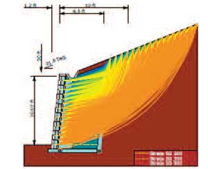
Figure 7.13 ICS Pressure Map Diagram
ICS will be run for the total height structure with slip arcs defined by entry nodes above the wall and exit nodes defined by each block course. For a gravity wall, the first entry node is 2 ft behind the face of the top block, whether it is a single or double wall or an AB Fieldstone long or short anchoring unit wall. For a No-Fines or geogrid structure, the first entry node is directly up from the back of the mass. The last entry node is always defined at the back of the Design Envelope defined by the greater of 2H or He + L, as discussed earlier. The number of entry points will equal the number of courses of blocks and be divided evenly between the first entry node and the back of the Design Envelope. Please note that when a CCS analysis is triggered the old method of Internal Stability Analysis will be disabled and you will be required to run ICS.AB Walls Design Software and the supporting Mathcad Hand Calculation file provides for the ability to use multiple soil types in both the reinforced mass and the retained soil. With the addition of the CCS analytics you are also able to define a depth of structure with the appropriate properties for these soil types. Being able to specify what type of fill material is being used and exactly where, provides for the full utilization of Internal Compound Stability calculations and allows the engineer to configure the elements of the structure to handle the localized loading. AB Walls Design Software contains a pressure mapping feature that provides a visual illustration of where the lowest factors of safety are, and thereby gives the engineer direct feedback on the critical aspects of their design. These features provide the engineer with a host of options to be able to develop a design, based on the specific challenges that are inherent to their project, that meets the needs of their specific project, is cost effective, and provides the owner with a safe structure. Running ICS for a CCS does not in any way replace the need to have a global analysis conducted to ensure the overall site stability is achieved.
Top of Wall Stability Analysis
The top of every structure needs to be investigated for overturning and sliding stability. This is the gravity portion of the wall that extends above the top layer of geogrid or above the top of the no-fines mass. The depth of this upper gravity wall section can be made up of standard wall units, double block units, or AB Fieldstone units using short or long anchoring units. AB Walls will run a standard overturning and sliding calculations based on all applied forces and resistance based on the facing depth.
AB Walls will take a conservative approach to this overturning calculation. The user has freedom to use double blocks or long anchoring units at any course they choose. Because of this, if the user has not input the same deep block for the entire height of this top portion of their structure, the resisting forces will be based on the single block depth, even if only one block is left short.
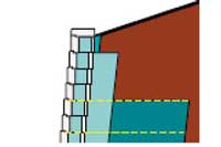
Figure 7.14 Standard Above Wall Config.
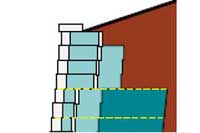
Figure 7.15 Long Anchoring Unit Above
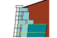
Figure 7.16 Irregular Config. Above
It should also be noted that seismic testing conducted in conjunction with Columbia University, (Ling, Lecshinsky et al. 2002), clearly indicated that extending the top layer or layers of reinforcement to 90% of the wall height prevented cracking during high seismic events at the back of the reinforced mass. Based on this testing, and performance in seismically active regions, it is our recommendation that in regions where high pseudo static loading is applied (horizontal acceleration coefficients in excess of 0.20g) that the Upper Structure should not be constructed with a mass depth that is less than 60% of the total wall height and whenever possible, at least one of the top layers of grid should be extended to 90% of the total wall height.
Overview of Design Methods and Tools
The design methods employed utilize the approach and equations contained in other chapters of the Allan Block Engineering Manual and focus them in a manner that is straight forward and consistent with what has been develop over the lifetime of the SRW Industry. In addition to AB Walls, a comprehensive design software for all aspects of technical analysis and creation of construction drawings, the accompanying Mathcad file provides the engineer with the ability to provide hand calculations and, if need be, alter any of the equations to fit their professional judgement for any given project. Contact the Allan Block Engineering Department for assistance or a phone tutorial that also will provide Continuing Education Units (CEU), accredited by IACET, for material covered
Examples of Complex Composite Structure configuration in AB Walls
Gravity Wall on Top of Geogrid Wall or No-fines Wall
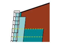
Standard gravity wall above geogrid wall
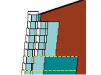
Double block or AB Fieldstone long anchoring unit wall above geogrid wall
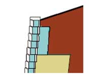
Standard gravity wall above no-fines concrete wall
Geogrid Wall Above or Below
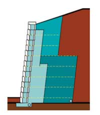
Geogrid lengths in the Upper Structure cannot be less than the standard minimum of 4 ft (120 cm) or 60% of the Upper Structure height
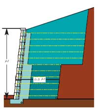
Geogrid lengths in the Lower Structure are recommended to be not less than 60% of the total wall height
No-Fines on Top or Bottom of a Geogrid Wall Structure
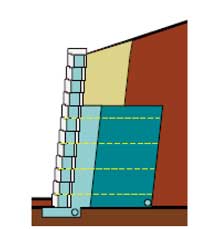
No-fines concrete in the Upper Structure cannot be less than the standard minimum of 2 ft (60 cm) and is commonly designed to be 40% of the Upper Structure height
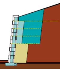
Lower no-fines structure depth cannot be less than 70% of the depth of the Upper Structure
No-Fines on Top and Bottom with Varied Depth
Although an unlikely scenario, AB Walls allows for varied no-fines depth in CCS structures.
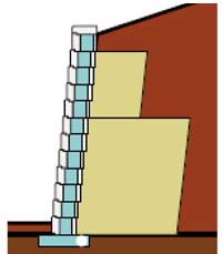
No-fines concrete in the Upper Structure cannot be less than the standard minimum of 2 ft (60 cm) or and is commonly designed to be 40% of the Upper Structure height
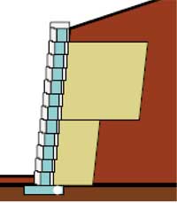
Lower no-fines structure depth cannot be less than 70% of the depth of the Upper Structure
AB Walls Design Software
AB Walls provides a tool to allow the engineer to analyze a Complex Composite Structure with limitations that we have stated in our description of our approach to analyzing this type of configuration. The following provides a review of some limitations that we believe to be judicious when designing a CCS. Some of these apply directly to a Complex Composite Structures, others are what we have found to be Best Practice for all SRW designs.
- We recommend the first layer of grid be placed on top of the first course of block, provide for some flexibility as a result of corners and step ups that may require placement on the second course, but flag designs that have the first course of grid being placed higher than 16 inches (40 cm) from the base.
- We recommend grid spacing a 16 inches (40 cm) maximum but flag designs with more than 24 inches (60 cm) spacing.
- For commercial walls we recommend the minimum length for primary reinforcements to be 4 ft (1.2m). The software does not allow you to reduce this length, but as the engineer you can use the included Mathcad file to adjust as you see fit based on your engineering judgement.
- Although structures have been routinely constructed in a manner similar to what we have covered, analysis has not been easily performed. For the purpose of our discussion we have limited the ratio between the Upper and Lower Structures to a ratio of 70% depth of the structure.
- Based on field experience and the advent of a more refined Internal Compound Stability Analysis industry recommendation are that the length of primary reinforcement should not be less than 60% of the total wall height as measured from the face of the block. The CCS approach allows the engineer to achieve a more detailed analysis when dealing with site obstructions.
- The analysis includes an external stability (overturning and sliding for both the Upper and Lower Structure) and factors of safety are reported. The software will not allow for the depth of either structure to be less than what is required to achieve a minimum factor of safety.
- When the Upper Structure is extends beyond the depth of the Lower Structure a bearing analysis is conducted to check for potential rotation and buckling at the intersection of the Upper and Lower Structures. The analysis will check the possible risk of differential settlement that could take place under the Upper Structure due to the unreinforced nature of the soil.
Sample Hand Calculations
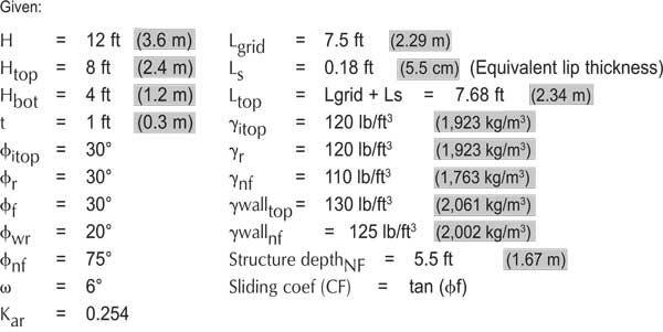
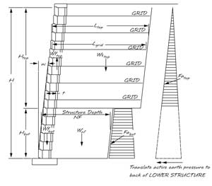
Example Section - Loads
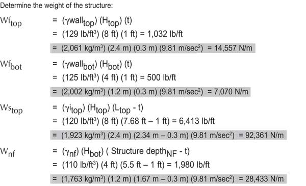
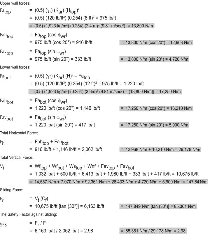
This example shows the overturning and sliding calculations for the Lower Structure with the Upper Structure applied as a surcharge. Please note that the overturning and sliding calculations for the Upper Structure will be calculated like any other structure except the upper wall toe will be the top of the lower wall. Therefore this point will become the rotational point for the calculations.
Sliding Calculations
Overturning Calculations
We will first start by determining the moment arms for each force.
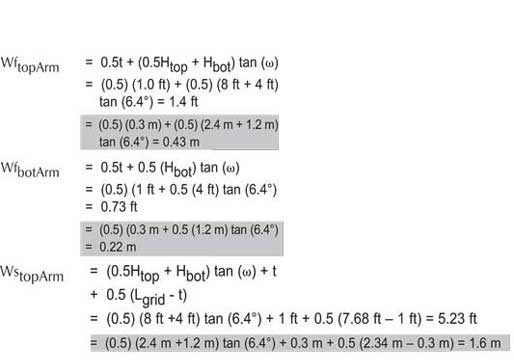
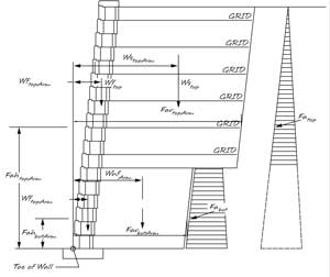
Figure 7.18 Example Section - Moment Arms
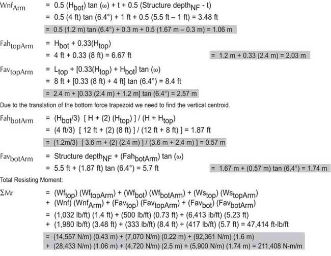

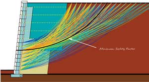
Figure 7.19 Example Section - Pressure Map - Min. Safety Factors = 2.71 - Course Six
The Pressure Map for this example from AB Walls shows all results well above the minimum of 1.3 and as expected the worst case arcs come in directly above the no-fines concrete mass.
Bearing Capacity Calculations
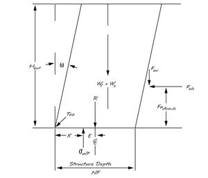
Figure 7.20 Bearing Capacity Diagram
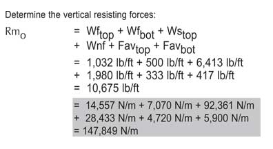
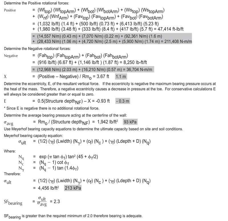
Bearing safety factors are very straight forward by determining the downward vertical force and comparing them to the bearing capacity of the site soils. Allan Block also calculates the forward rotational forces and if they are positive, they are added to the bearing forces. The first step is to determine the eccentricity of the structure.
