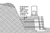
Compact in 8 in (200 mm) lifts, one course at a time
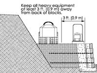
Keep all heavy equipment at least 3 ft (0.9 m) away from the back of the blocks
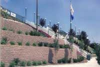
Terraced Retaining Wall
Clay Soils
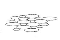
- Small
- Flat
- Smooth Surfaces
Sandy Soils
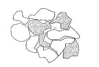
- Large
- Spherical
- Angular Surfaces
Retaining Wall Compaction, Geogrid Spacing, and Geogrid Length
Engineers have the responsibility of designing cost effective structures that are safe and reliable. On the surface this task seems to be relatively straight forward and one that can easily be quantified. The questions that must be answered to achieve this design standard will determine how complicated this process will be.
What forces will be applied to the structure? What materials will be used to build the structure? Are there other elements that may affect the performance of the structure? During the construction process what safeguards will be in place to ensure that plans and specifications are followed? What will be required after completion of the project for the continued safe reliable performance of the structure? What has our experience told us about what can go wrong in real life?
These questions have led to a series of changes over the last fifteen years in the design of segmental retaining walls. Allan Block has helped to drive the industry to ensure cost effectiveness with safety and reliability. During this time frame many things have evolved, and design refinements are producing a better final product that suits the needs of our customers.
From our field experience and full scale testing we have arrived at conclusions that change how we approach designs. This does not imply that the structures built over the last fifteen years are not safe, but rather we have determined that with a few simple changes we can build safer yet still efficient retaining wall structures.
Compaction:
Geogrid-reinforced structures are designed to perform as a composite structure. In order for them to perform in this manner, consistent compaction is mandatory. Actual installations are plagued with improper compaction due to soil lifts in excess of the maximum 8-inch (200 mm) lifts. Tighter specifications should be used on compaction and field testing requirements.
Geogrid Spacing:
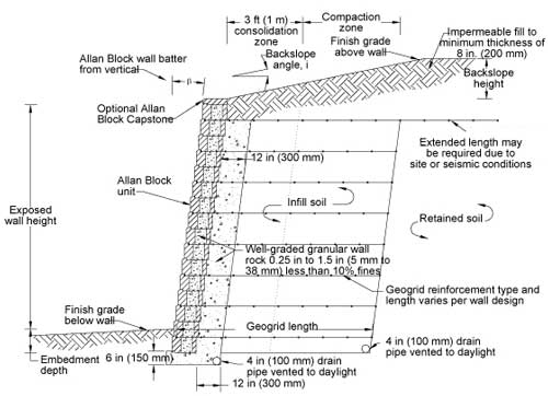
Typical Retaining Wall Section with 2 Course Grid Spacing
Compound failure planes may develop when the reinforced mass is constructed with geogrids that are not spaced closely enough together. Allan Block recommends geogrid spacing of sixteen inches or less using light weight geogrid-reinforcement. This is a more efficient way to distribute the reinforcement throughout the mass, which develops a more coherent structure. Lower strength geogrid is typically less costly therefore the project budget is usually not affected by the increased total amount of geogrid.
Geogrid Length:
We have concluded that grid lengths between 50 and 60 percent of the wall height will provide a safe and efficient structure, but for simplicity we are recommending 60 percent as the typical grid length for a starting point. The exception is the top layer of grid which should be extended to intertwine the reinforced mass with the retained soil mass. This eliminates potential for soil cracks at the intersection of these two masses. Extending the grid by approximately 3-feet (1 m), or to 90 percent of the wall height in seismic zones, should accomplish the goal of tying the reinforced mass with the retained mass.
Infill Soil:
On-site soils may be used as infill soil if they are of sufficient quality. Stay away from high plastic clays in the reinforced soil mass and use granular material whenever possible. When clay soils are used in the reinforced zone extra precautions should be employed to keep water from penetrating the mass.
Water Management:
The addition of water to the reinforced soil mass can change the soil properties dramatically. Designers need to understand and control surface and subsurface water flows. Wall rock and toe drains are intended for incidental water only, any excess water should be routed away from the reinforced soil mass.
Issues of design and construction will always be an ongoing evolutionary process. To accommodate this Allan Block has and will continue to invest in obtaining data from new experiences and full scale tests.
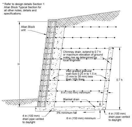
Chimney Drains
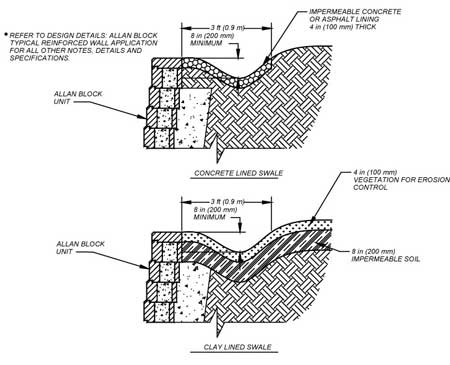
Swales


