AB CADD Import Functions
Navigate into the Wall Manager page of AB CADD
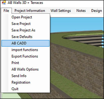
- File -> AB CADD
- Home Page -> AB CADD
- Elevation Page -> AB CADD
Import a site plan into AB CADD
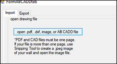
- “Open .pdf, .dxf, image file, or AB CADD File” button
- Select the file of your site plan:
- This will import the site plan into the user’s AB CADD model space
- You can open pdf, dxf, image files, and existing AB Cadd Files.
- If you open an existing AB CADD file, all of your saved data will be loaded into the import pages.
- Any files brought in must be only one page. If the file you are using is more than one page, you must either break the document into separate pages, or create an image file of the area you need by using the snipping tool.
Drawing Scale
- Here we will set the scale of our file that we opened in AB CADD.
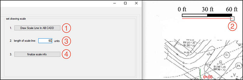
- Click the “Draw Scale Line” button.
- This will prompt you to draw a line in the AB CADD model space.
- Find a component of the drawing that has a known dimension/measurement (Something like a scale bar or a called-out measurement).
- Click once at the start of the measurement and click a second time at the end of the measurement. After clicking the second point, press “enter” on the keyboard with the mouse on top of the 2nd point. This should draw a line between the two points.
- After your line is drawn, jump back into the import page and type in the desired length of the line you just drew.
- Once your line is drawn and the length is entered into the text box, click “Finalize scale info”. This will set your scale for all walls on the project.
North Arrow
- Here we will set the direction of North on our site plan. This will be used on the AB Construction Export.
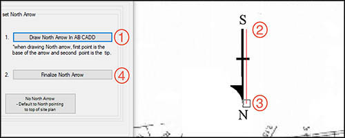
- Click the “Draw North Arrow” button:
- This will prompt you to draw a line in the AB CADD model space.
- Draw a line in the direction of South to North (click once on the South point of the North arrow, and a second time on the North point of the North Arrow).
- Once your line is drawn, click the “Finalize North Arrow” button in the import page. You will get a confirmation of the angle you drew. The angle shown will measure from the left (If your north arrow points straight up on the page, the angle shown would be 90 degrees).
- If you do not have a north arrow on the site or you are not sure which direction is North, you will need to click the button at the bottom of the page to create a default North direction (North in the direction of the top of page).
- You can now move on to the next portion of the import pages.
Draw Walls
- Follow the instructions to draw a line tracing your wall(s) in the AB CADD model space.
- Click “Draw Wall” and trace your first wall on the plan that you imported.
- Once you have finished tracing your wall click Enter on your keyboard while the mouse is covering the last point you clicked.
- The wall has now been traced.
- Select one of the line segments on the wall you just drew.
- With one of the line segments selected, navigate back to the import page and type in the desired name for your wall.
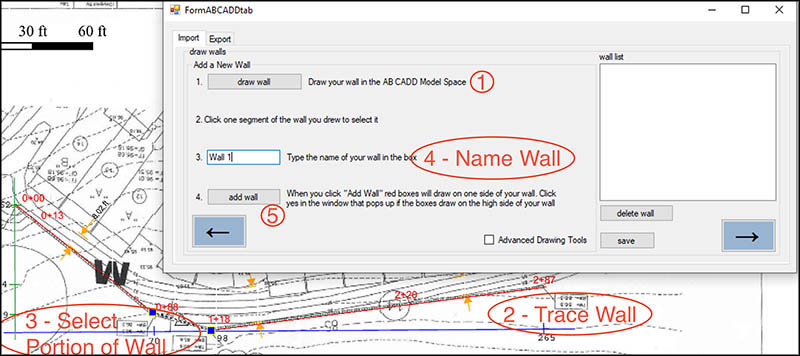
- With the wall segment selected and a name for the wall typed into the message box, click the “Add Wall” button.
- When you click add wall, your model space in AB CADD will automatically zoom in to the extents of your wall.
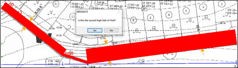
- The software will draw red rectangles on one side of the wall and a prompt will pop up asking if the red boxes are on the high side of your retaining wall.
- If the boxes draw on the high side of the wall, click “Yes” and your high side will be set.
- If you click “No” the software will flip which side is the high side automatically and you do not need to do anything else here.
- You can now repeat these steps as many times as you would like to add more walls to your project.
- Be sure to give your walls different names so that two walls are not named the same thing.
- If you would like to delete a wall, all you have to do is select it in the box on the right side of the page and click the “Delete” button.
- You can now move on to the next page with the arrow pointing to the right.
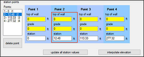
Define Points on Walls
- On this page we will be adding points to our wall and setting the elevations of those points. This is also where we will finalize the wall and load the information into AB Walls.
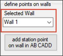
- Make sure that you have the correct wall selected in the dropdown list in the upper left of the page.
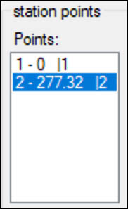
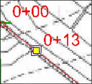
- You will notice that when you select the wall, there should already be two points showing up in the “Points” box in the middle of the page. These are the first and last points of our wall.
- Click each of these points and confirm that they are in the correct locations.
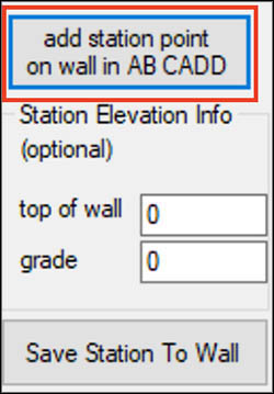
- In order to add more points to our wall, you will need to click “Add station point on wall in AB CADD”.
- This will prompt you to add a point in AB CADD.
- When move your cursor near your wall, the point should snap to the wall.
- Move your mouse to the desired point location and click once. This will place your point.
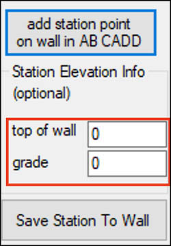
- With the point drawn and selected, navigate back to the import page. You will now see two text boxes labeled “Top of wall” and “Grade”.
- If you would like, you can now enter both top of wall and grade elevations info for the point that you just added.
- If you do not have the information or would like to add elevation info later in the process, just skip filling in the box.
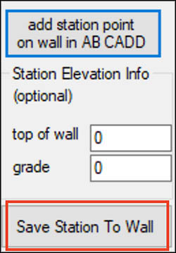
- With your point information inputted, click the “Save Station to Wall” button. This will save the point you just created as well as any elevation info you inputted.
- Repeat these steps for any other points on your wall.
- As you add points, you will notice that a box on the right updates with info on each of the points. If you would like, you can modify elevation info in this box.
- To modify elevation info in the “Station points” box, all you have to do is type values into the “Top of Wall” and “Grade” boxes.
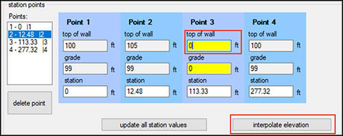
- If you are not sure of the elevation of a point but you know that the elevations of the wall transition smoothly between points you can use the “Interpolate elevation” button.
- To use the “interpolate elevation” button, all you have to do is click into the box you would like to interpolate and click “Interpolate Elevation”.
- This will take the known stationing and elevation info of the points in front and behind the selected point and create a smooth elevation transition at your selected point.
- Once you have modified your points in the “Station Points” box and would like to finalize the elevations you entered, just click the “Update all station values” button. Your wall elevations are now saved.
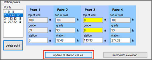
- Cycle through the walls on your project and repeat the above steps to set elevations for each wall.