Print Case Study
Project Information
Name: High Pointe Commons
Harrisburg, Pennsylvania
Product: AB Classic
Size: 24,500 AB Units, 18.0 ft (5.48 m) max. height
Local Engineer: Merle Seville PE, Keller Engineers Inc.
General Contractor & Wall Builder: High Construction, Inc. & K & M Dri-Lay Masonry, Inc.
Allan Block Manufacturer:
Nitterhouse Masonry Products, LLC -Chambersburg, Pennsylvania
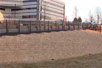
High Pointe Commons is a 6 retaining wall project that surrounds a large commercial development area
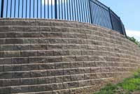
The majority of the retaining walls had either paved surfaces or slopes above them, so surcharge was a big factor
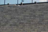
A preconstruction meeting was held to discuss and coordinate the construction and staging of the retaining walls to keep this large wall prject running smoothly
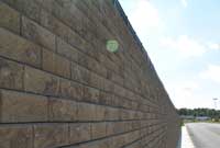
Construction of retaining walls this large can be built efficiently using a separate base and wall crews. This speed up the installation process
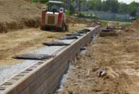
Lengthening the top layers of geogrid when paved surfaces are above helps to minimize the potential of future cracking in the retaining wall
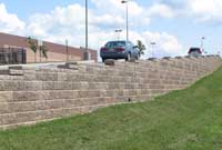
On this project the on-site soils were approved for use, but this is not the case with every project - check with the site engineer for requirements
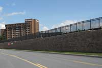
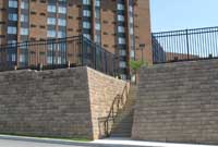
This project called for over 2000 ft (610 m) of fencing or handrails to be installed after the retaining wall construction was complete
Large Retaining Wall Project Comes Together with Good Planning
High Pointe Commons is a large project with 6 different retaining walls totaling more than 24,000 ft2 (2230 m2). The largest wall is over 18 ft (5.48 m) tall and 710 ft (216.4 m) long. Although large, a wall such as this is fairly straight forward to plan, design and build. Walls, big or small, have the same questions to ask, how tall does it need to be, how long should the geogrids be, are there slopes above or below, and are there surcharges above and what are the soil conditions? Finding specific answers for these generic questions would allow any engineer to design a wall just like this one. This profile will discuss planning and designing of three particular aspects, small slopes below, surcharges above and planning and installing fence footings.
Plan
High Pointe Commons is a large multi-faceted commercial development with shops, restaurants and a larger up scale Sheraton Hotel complex. The plan for a site as large as this requires the coordination of utilities, water management items such as storm pipes and manholes, traffic flow patterns and many other things long before any construction can begin. Retaining walls can play the essential role in making all of these site development issues successful.
A wall design engineer reviewing the site plans must not only recognize and plan for the simple, accepted design issues such as geogrid lengths and spacing, but also the more complex such as detention basins and structures within the geogrid zone. A careful methodical review of the site plans and a visit to the site, paying attention to a Wall-Design Checklist (page 11 of AB Spec Book), will help minimize future unknowns in the design and construction process. The main purpose of a wall design checklist is to help the design engineer ask the right questions and to make the design process run smoothly. Additionally, Allan Block has a Construction and Inspection Check List to assist the contractors and engineers with preconstruction meetings.
Design
Consider the 18 ft (5.48 m) tall by 710 ft (216.4 m) long retaining wall shown here. It was built with AB Classic block which has a nominal setback of 6 degrees. It has a flat top with a heavy traffic surcharge above and a relatively short 2:1 slope below. When designing a wall with a slope below, the engineer must always consider the stability of the slope. Even a relatively short slope, such as this one, can have problems if the wall is not built deep enough into the slope so the toe of the wall does not become undermined or slip out. Depending on the soil type and slope a global stability analysis may by necessary using a computer program specifically designed to model slopes. For this discussion we will discuss simple undermining. A typical amount of buried block for a wall with no slope below would be roughly equal to 1 inch (25.4 mm) of buried block for every 1 ft (0.3 m) of wall. So our example 18 ft (5.48 m) wall would have about 18 inches (0.45 m) of buried block, but that would not provide much resistance to undermining.
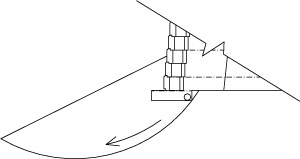
Typical Amount of Buried Block = smaller slip arc
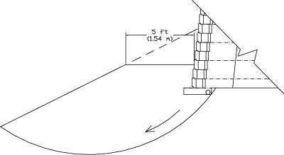
5 ft (1.52 m) Bench = greater slip arc
When a slope is below a wall you should consider using a 5 ft (1.52 m) soil bench at the base of the wall. Reviewing the two drawings shows that a 5 ft (1.52 m) bench provides a deeper wall rock base and a much greater slip arc to resist undermining than does the typical amount of buried block. Remember that with a 2:1 slope below and a 5 ft (1.52 m) bench the wall would need 2.5 ft (0.76 m) of additional height. This 2.5 ft (0.76 m) along with standard buried amount makes our 18 ft (5.48 m) exposed example wall closer to 23 ft (7.0 m) for design.
A typical design section for a wall such as this one would be similar to this section from AB Walls Design Software. The standard grid lengths would be around 60% of the total wall height and the top few layers of grid, depending of the wall height, would be lengthened to 90% of the total wall height due to the paved surfaces above. It is common practice to lengthen top grids for three distinct conditions:
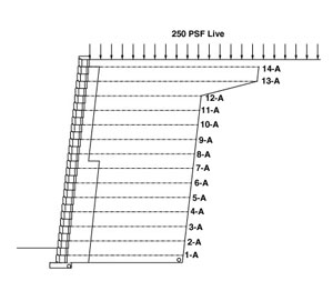
Typical Section
- Seismic loading
- Slopes above a wall
- Paved surfaces that are placed above the joint between the infill and retained soil zones.
At High Pointe Commons the majority of walls had either paved surfaces or slopes above them. AB Walls Design Software allows the engineer to model the wall section with elongated top grids under all surcharge conditions. With this flexibility, the user can attempt to model the design as close to as-built conditions as possible. The reason to lengthen the top grids when paved surfaces are above is to minimize the potential of future cracking in the retaining wall.
Cracked pavement can shorten the life of the pavement but also the life of the retaining wall by allowing water to migrate through the crack into the infill zone which could cause hydrostatic pressure to build up behind the facing. An engineer should consider the reinforced soil mass and retained soil mass as separate structures working independently. Although there is no relative movement between the two zones, a defined construction joint remains because the reinforced soil mass, formed by the Allan Block facing, the infill soil and the geogrid working together as a single unit is built with a tighter control on compaction. Whereas the retained soil is typically unreinforced re-compacted site soil built with less controls. By bridging the construction joint between the soil zones with extended geogrid layers you disrupt any variations between them, such as settlement, and minimize the potential of future cracking of the paved surface and ultimately increasing the life of both the pavement and the retaining wall.
Build
For projects of any size, but especially for ones as large as High Pointe Commons, all responsible parties should convene at a preconstruction meeting to discuss and coordinate the construction and staging of the walls. From excavating, utility installation and material storage to railing installation and final grading everyone needs to coordinate their efforts to keep the project on schedule. Once the initial excavation is complete, construction of walls this large can be built efficiently using a separate base and wall crews. On long flat walls such as these, a base crew should start in the middle and work in both directions. Once the base course is complete they can move on to the next wall while the wall crew can start to build the body of the wall one course at a time. Having two crews running will greatly increase the speed and efficiently of the construction.
The site engineer approved the use of site soils as infill soils. It is important that the installer not assume this is acceptable for every wall. The engineer must approve the reuse of the excavated material and if they do, a careful staging plan for the approved material should be implemented.
When reinstalling soil, a contractor must build the wall and backfill in one course increments. These maximum lifts of 8 inches (0.20 m) are important for proper compaction. Installers should verify with the engineer what level of compaction is required. A common value is 95% of Standard Proctor. Typically, a site this large would have an on site soils engineer to frequently test the compaction. Only light weight compaction equipment can be used within 3 ft (1 m) of the back of the wall facing and may require shorter lifts to meet the approved compaction level.
This project called for over 2000 ft (610 m) of fencing or handrails to be installed after wall construction. Once again, during the preconstruction meeting the engineer, wall installer and railing installer should coordinate their efforts. This small amount of extra time and coordination can save immeasurable time and prevent potential problems for the completed project. If the wall installer works with the designer and railing installer, a depth and location of each post footing can be worked into the wall construction. Going back after the wall is complete to install the post would most likely require hand digging as power hole augers can damage the geogrid to a point of needing replacement.
No matter what the size of your project, planning ahead and taking a methodical approach to design and construction is the key to building a quality structure with a lifetime of service.

