
Print Case Study
Project Information
Name: Skyline Ridge
Springfield, New Jersey
Product: AB Classic
Size: 75,000 AB Units, 70.0 ft (21 m) total wall height 90 ft (27 m) grade change
Local Engineer: Fred Porcello, P.E., Porcello Engineering
Site Civil Engineer: Casey and Keller, Inc.
Wall Builder: Pillari, LLC
Allan Block Manufacturer:
Clayton Block - Edison, New Jersey
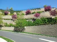
The retaining walls support the parking lots and recreational areas and in some areas support the condos themselves
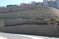
Terraced walls were chose to enhance the landscape and provide a plateu for the the condos to be built on
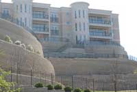
Global stability was an improtant factor in designing these walls to ensure the project was sucessful
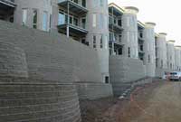
Many of the smaller walls above were directly incorporated into the building’s esthetic design
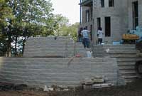
Detailed installation features were added to the upper walls such as stairs, railing and planters
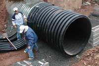
An air ventilation system for the underground parking garage was incorporated into the retaining wall construction
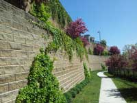
Retaining Walls Bring Living to New Heights
The Skyline Ridge development is a large residential community with 90 luxury condominiums overlooking the Manhattan skyline. The original site was very hilly and provided no quality space for building. The solution was a set of large Allan Block walls built to form a construction plateau. The project has 17 Allan Block walls consisting of more than 75,000 AB Classic block and a maximum grade change of 90 ft (27 m).
Plan
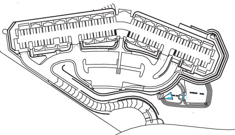
Site Plan
A project as large and complex as Skyline Ridge takes careful planning and coordination from the beginning. The site civil firm, Casey and Keller, started with the basic need for a large flat area to build the condominiums. They could have chosen to build one tall wall around the site, but the Owner, Garden Homes of Short Hills, New Jersey, chose to break the height into shorter terraces with accenting landscaping on each level. The walls not only provide the necessary grade change, but also support the parking lots and recreational areas and in some areas support the condos themselves. By allowing adequate time to plan the site, Casey and Keller, Inc. was able to plan for the building footings above the reinforced soil mass and for the required utilities and their placement locations and produce a detailed water management plan for the site.
Most of the utilities were brought to the site under the single access road leading in and out of the property. This was done in part to avoid potential interference with the reinforced soil masses of the wall structures. The site drainage is handled with many drop structures, all draining to a large detention basin near the lowest part of the project. Most of the drop structures were built outside the reinforced soil mass, but one needed to drop down through the mass and out the face of the wall. By having an early plan, Casey and Keller was able to highlight this drop structure for the wall designer to incorporate in the wall construction details.
Design
Plan Drawing
Porcello Engineering was contracted to design the Allan Block retaining walls because of their familiarity with SRW design and construction. They had designed many Allan Block walls, but these were different, as they were very tall and they supported the buildings directly on top of them.
Before starting the design, Porcello coordinated the building loads with the designer and did a thorough review of the geotechnical report to determine the quality of the site soils. The buildings were supported on spread footings which would be applied to the walls designs as dead load, and the site soils were very high quality gravels and sands which could be reused as backfill. In tall wall construction it is very important to use high quality compactable soil with a low plasticity index (PI) to minimize the potential for future settlement. Because of the requirement for high quality material and high levels of compaction Porcello and the owners called for an on-site soils engineer to monitor the soil compaction and wall construction.
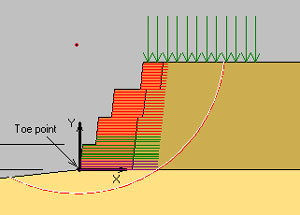
Porcello used AB Walls Design Software for their initial design of the walls and ReSSA to model the walls for global stability. It is important when designing any wall, but especially for tall walls, to consider global stability. For this site, the global model dictated the lengths of the geogrids in the lower walls. Once the grid strength and length were set in ReSSA, these final values were entered back into AB Walls 2007. Then AB Walls 2007 was rerun for wall safety factors and quantities. The combined power of programs like AB Walls 2007 and ReSSA give engineers like Porcello the tools to model walls of virtually any size.
Build
Pillari, LLC, an Allan Block certified wall installer, was contracted to build the walls. They are a large construction company with the manpower and equipment to handle a project of this magnitude. They worked directly with Porcello for the wall construction, but because of the integration of the walls into the building plans, coordination with all disciplines was mandatory. The project owners and designers called for a preconstruction meeting to get the project started in the right direction and weekly site meetings to ensure the project went smoothly and stayed on schedule.
During the beginning of the project the focus was on building as much wall as possible and getting the utilities in place. The lower walls were between 10 (3 m) and 20 ft (6 m) tall which under normal condition would have grid lengths between 60 and 80% of the wall height. These, however, were the base for a terraced structure reaching a height of 70 ft (21 m) so the extremely long grid lengths posed a challenge to Pillari. Pillari was careful to install the grid correctly by first connecting it to the facing and then pulling it back and staking it tight. They were also careful when placing the infill material; they always started at the facing and filled back towards the tail of the grid layer. This way, the natural placement and compaction of this material would act to pull the grid and facing tight into the soil mass. If an installer places the infill material starting at the tail of the grid and works towards the facing, slack will appear in the grid layer at the facing.
As they reached the top of the plateau, the building construction started and the wall progress slowed to accommodate more detailed installation such as stairs, railing and planters. Many of the smaller walls above were directly incorporated into the building’s esthetic design, so Pillari had to stage their work around the building’s construction.
One of the more interesting aspects of the wall construction, as it related to the building construction, was the incorporation of an air ventilation system for the underground parking garage. The design called for a 4 ft (1.2 m) round air duct with a concrete headwall build into the Allan Block wall. The installers built the Allan Block walls up to either side of the duct to help form the sides of the headwall, then the bottom and sides of the headwall was formed and cast. The Allan Block walls were then built up to a point level with where the top of the headwall will be. A last headwall pour was cast to bring the headwall up level with the top Allan Block course. Pillari used the same building technique they would if the duct had been a large drain pipe of culvert.
No matter what the size of your project, planning ahead and taking a methodical approach to design and construction is the key to building a quality structure with a lifetime of service.
This project called for over 2000 ft (610 m) of fencing or handrails to be installed after wall construction. Once again, during the preconstruction meeting the engineer, wall installer and railing installer should coordinate their efforts. This small amount of extra time and coordination can save immeasurable time and prevent potential problems for the completed project. If the wall installer works with the designer and railing installer, a depth and location of each post footing can be worked into the wall construction. Going back after the wall is complete to install the post would most likely require hand digging as power hole augers can damage the geogrid to a point of needing replacement.
No matter what the size of your project, planning ahead and taking a methodical approach to design and construction is the key to building a quality structure with a lifetime of service.
