Technical Newsletter
Issue 11
Project Information
Name: Okanagan Lake
West Kelowna, British Columbia
Product: AB Classic
Size: 6500 ft² (604 m²) 44 ft (13.4 m) maximum height
Local Engineer: Ron Campbell, Cascade Geotech
Wall Builder: Sunnyslope Landscape & Custom Design
Allan Block Manufacturer:
Expocrete - Richmond, British Columbia
Tieback Description
Tiebacks can be installed in sufficiently competent rock and most types of soil except soft clays and silts. The capacity of the anchors in soil will vary greatly depending upon grain size and installation method. The denser, granular soils will typically produce higher capacity tiebacks. Just as in a traditional grid reinforced wall, the wall designer must have a good understanding of the loads and the physical properties of the soil or rock.
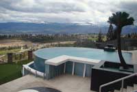
Above Grade Pool
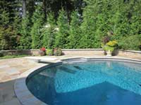
Below Grade Pool
(Self Supporting)
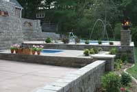
Below Grade Pool
(Supported by Site Soils)
Building Retaining Walls on Steep Slopes
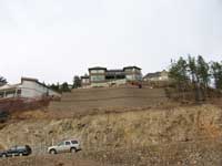
The Tocher residence is perched on a small plot of land that overlooks Okanagan Lake in West Kelowna, British Columbia. Although the location provided beautiful vistas, the steep slopes and small lot size limited use of the tiny backyard. For the Tocher’s, the plan was to replace the smaller retaining wall located close to the house with a substantially larger wall near the property line to create enough useable space to install a swimming pool.
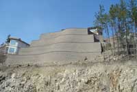
The walls had to handle more than 40 ft (12.2 m) of grade change from the back property line to achieve the desired height. Local ordinance allowed for exposed wall heights up to 8 ft (2.4 m) with at least 6 ft (1.8 m) between tiered retaining walls. To achieve their goals and adhere to the local ordinance, it required the installation of five retaining walls - four of the walls were 10 ft (3 m) tall and one was 4 ft (1.2 m) tall with a slight slope between walls to meet the 8 ft (2.4 m) exposed height limit.
Due to the close proximity of the rock outcroppings, the lowest wall had to be anchored to the rock face with 1 in. (2.5 cm) stainless threaded rods. The rod was inserted into a drilled hole in the rock face and epoxy grouted into the hole. The rod was attached to a 3 in. (7.6 cm) schedule 40 galvanized pipe with the geogrid extending from the wall, wrapping around the pipe and extending back toward the wall to the next course above.
The second wall would utilize geogrid to reinforce the wall in lengths of 32 ft (9.8 m), where space allowed, and pinning to the rock face where insufficient clearance occurred. Subsequent walls above would also be reinforced with geogrid.
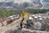
Sunnyslope had to blast, jackhammer and excavate rock to create a solid, level ledge within the bedrock. Although blasting required additional work, the blasted rock left behind provided good granular material to be used as infill behind the wall. Very little fill needed to be brought on-site to complete the job.
The Tocher’s small backyard, with a few plantings, a small sitting area and strip of grass was transformed into a magnificent outdoor living space, complete with a pool, pool house and an artificial putting green. The new wraparound pool deck and patio now provides the Tocher’s family and friends a great place to enjoy the view of the valley below. For more information on this story, check out the case study Terraced Walls - Okanagan Lake - West Kelowna, BC.
Alternative Reinforcing Options for Retaining Walls
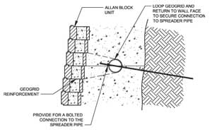
Anchor Connection
The Tocher Residence was an interesting project in many ways, but the bottom terrace and the alternate reinforcing options begs for a greater discussion. Building in and around solid rock has benefits and challenges. Solid foundations without settlement and virtually no lateral pressures for the retained soil are benefits. Blasting rock, having no room for geogrid and trying to level block on uneven bedrock are some of the challenges.
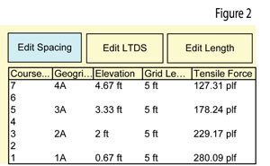
For this project, the designers used drilled in rock anchors with a horizontal spreader pipe. The pipe is placed so the installers can extend the geogrid layers from the wall, wrapping it around the pipe and placing it between subsequent course of block above, as shown in Figure 1. The design of the pipe is the limiting factor to the system because the rock anchors have a tremendous capacity compared to the bending capacity of the pipe. Therefore, the spacing of the anchors must be determined based on the strength of the pipe. To determine the uniform load on the spreader pipe the designer can use the applied loads from a typical geogrid design from AB Walls 10 Design Software. For instance, Figure 2 is the Internal Forces from AB Walls 10, if the pipe is placed between layers 1A and 2A, the applied loads for those two layers can be added together for a total applied uniform load of 509.26 plf (7.4 kN/m). Similarly, 3A and 4A would yield 305.55 plf (4.5 kN/m). This is a conservative approach because the geogrid design section from AB Walls 10 cannot model a solid rock retained soil. The designer could run their section with a very high friction angle for the retained soil to lessen the applied forces.
Leveling the base course on uneven rock is similar to cutting the block to shape it around a large diameter pipe. The installers should cut the bottom of each block to closely match the jagged shape of the bedrock to allow the leveling of that course. In the Tocher project there was no buried block because of the rock ledge, so the design needed to transfer the sliding or shear forces directly into the rock. They had the installer drill and grout in short pieces of rebar to act as shear pins at block core location. To install the bottom block course, they placed the shaped block into a mortar bed that supported the block until the block and mortar was solid enough to continue with additional courses.
Designing Retaining Walls for Swimming Pools
After the wall was completed at the Tocher residence, the engineer was asked if it was possible to construct a pool above the wall. After re-evaluating the loads and wall design, it was determined to be feasible and the pool was built. So what did the engineer have to consider when the pool request was made? Well, the answer really depends on the type of pool. Pool structures can be above ground and self-supporting (using sidewalls), in-ground and self supporting, or an in-ground structure reliant on the native soil to support the water's weight.
Above Grade Pool
This is the easiest scenario since the entire pool is above ground. You simply need to accommodate the additional weight from the pool itself. By taking the pool depth and multiplying it by the unit weight of water, the surcharge can be modeled and the wall’s safety factors can be verified. This is easily done by using the surcharge options within AB Walls 10 Design Software.
Below Grade Pool (Self Supporting)
Understanding the pool structure will be required to confirm whether it is self supporting or relies on the site’s soil. The walls of a concrete and gunite pools can be designed and reinforced to accommodate the lateral forces associated with the pools. These forces change when the pool is in use or empty. When the pool is full of water the hydrostatic forces from the water must be retained and when the pool is empty the soil pressures must be considered or the pool will collapse. If the pool is self supporting and retains these lateral pressures, adding a load or surcharge on the retaining wall is not required, but understanding the construction sequence and how it might influence the wall needs to be considered. A temporary construction surcharge may be required.
Below Grade Pool (Supported by Site Soils)
A pool that requires the lateral support of the surrounding soil will add a tremendous amount of pressure to the wall. These pools are typically constructed using fiberglass walls or a vinyl liner over a metal, wood or plastic frame. The extra lateral pressure may result in a retaining wall design with additional grid layers and/or length or possibly no-fines concrete for stability. A basic recommendation would be to keep the pool a distance of at least twice the wall height to keep the load from influencing the wall.
Always Consider Drainage
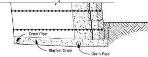
Additional consideration should be given for back up drainage needs in the event the pool system springs a leak. The addition of chimney and blanket drains could capture the water before it has a chance to saturate the soil behind the wall.
