Technical Newsletter
Issue 25
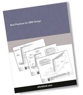
Best Practices for SRW Design
Allan Block Corporation has been a leader in the SRW industry since the company was founded nearly 30 years ago. We have pushed the areas of design, construction and research to better the entire industry. We work closely with the Concrete Masonry & Hardscapes Association (CMHA) and leading academic research professionals to advance the industry as a whole. With all our past experience and high quality partnerships, Allan Block Corporation has published a Best Practices for SRW Design manual. This newsletter will highlight only a small portion of the document.
The document is meant for all SRWs including both residential and commercial applications and is set up in twelve comprehensive chapters.
- Design Guidelines and Pre-Const. Considerations
- Typical Wall Construction
- Water Management – Typical
- Water Management – Alternate Drain
- Water Applications
- Soils and Compaction
- Geogrid Reinforcement
- Tall Wall Considerations
- Global Stability - General
- Global Stability – Terraced Walls
- Seismic Considerations
- Above Walls Considerations
The intent of the Best Practices document is to communicate the best practices for design of segmental retaining walls (SRW) and to establish a path towards a goal of Zero Wall Failures as a result of product quality, design, and construction. This document is not meant to be a final authority as each project has its own set of unique situations. The local engineer of record must use their best engineering judgment to account for those situations that present themselves and to provide a safe and efficient design for the customer. It is the recommendation of Allan Block Corporation that the local engineer of record work for and be paid by the project owner.
It has been our experience that the local engineer of record should be the project site civil engineer as they are best suited to take responsibility for the design, and how it affects the site. Whether they do the design in-house or use an outside consultant to do the design for the project it is up to them. The project site civil engineer has control of several of the overall aspects of the project and therefore is most able to properly handle the integration and communication required to ensure the performance of the wall complies with the needs of the site. For wall design applications that are outside of the experience level of the project site civil engineer, a wall designer with the appropriate knowledge and experience should be contracted with by the project site civil engineer. It is recommended that the wall contractor not be responsible for securing the engineering. At no time does the contractor or local building official have the authority to override the approved plans and specifications provided from the local engineer of record.
DESIGN GUIDELINES
Design guidelines range from understanding the reason for the wall, to details on methodology, geotechnical reports, soils parameters, site plans, site drainage, loading conditions, scope of responsibility, unit specifications, required product durability, construction drawings, site visits, and a formal construction review process. Although each of these areas are expanded on in other documents, special consideration should be paid to site soils and soils used inside the reinforced mass. While cohesionless, free draining materials (less than 10% fines and/or PI less than 6 and LL less than 30) are preferred in the reinforced mass, soils with low plastic fines (i.e. CL, SM, SC with PI less than 20 and LL less than 40) may be used for SRW construction provided other details are incorporated into the design to minimize infiltration of above grade or below grade water sources.
TYPICAL WALL CONSTRUCTION
Typical wall construction includes all aspects of any wall, whether typical or complex. The items that need considerations include but are not limited to the following: soils below the wall, allowable soils used in the reinforced mass, wall rock column size and material type used, verification of all soils used, wall embedment depth, base size and base material verification, minimum geogrid lengths, initial location and spacing requirements of geogrid layers, compaction level requirements, and capping requirements.
In the cores of hollow SRW units and a minimum of 12 in. (30 cm) directly behind the wall there is a need to place and compact wall rock. Wall rock can be defined as well graded compactible aggregate ranging in size from 0.25 - 1.5 in. (6 - 38 mm) with no more than 10% fines. The intent of this column of rock is to aide in the compaction directly behind the wall, to reduce the possibility of down drag forces on the geogrid, and to provide a channel to remove incidental water that migrates to the face of the wall.
Geogrid lengths are measured from the front face of the wall and are typically not less than 60 percent of the total height of the wall structure. Geogrid should be positioned to start on top of the first course of block. Geogrid spacing is recommended to be at 16 in. (40 cm) or less. This is reduced from the industry standard minimum spacing of 24 in. (60 cm) based on performance during full-scale seismic testing, collective findings of FHWA GRS/IBS research programs, ICS design analysis, and favorable observations of wall performance on walls with tighter grid spacing.
TALL WALL CONSIDERATIONS
Tall wall considerations are to be employed with structures rising to a height of between 10 – 15 ft (3 – 4.5 m) or taller, depending on the application and the discretion of the wall design engineer. A 10 ft (3 m) high wall structure with a slope or structure above would be considered as a tall wall, while the same wall height constructed with a level condition above the wall without any additional surcharge may not require consideration as a tall wall.
WATER MANAGEMENT
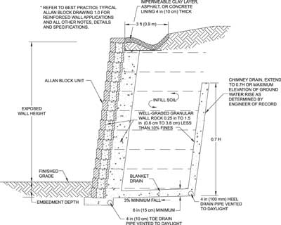
Water Management must be addressed as typical design methodologies do not take into account hydrostatic forces. Therefore, a proper design must identify and make provisions to capture water and move it away from the reinforced mass. From identifying water sources, to utilizing a combination of blanket drains and chimney drains, placement of drainage pipes, to above grade water management, such as drainage swales, each of these items must be addressed to capture and route the water to minimize its potential impact on the wall structure.
GLOBAL STABILITY
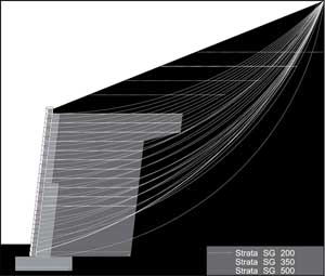
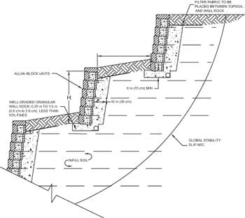
Global stability is often times an overlooked portion of SRW wall design. As a general rule. all walls with a slope below the wall, a slope above the wall, or terraced applications should be subject to a global analysis. For walls with slopes below, local ordinances commonly reference to bury sufficient blocks to have a 5 to 7 ft (1.5 to 2.1 m) level bench in front of the wall.
AB WALLS DESIGN SOFTWARE HAS BEEN UPDATED!
AB Walls Design Software is a comprehensive design tool which outputs professional quality construction drawings, along with the technical support data. This program allows designers to transfer a conceptual layout from a site plan to a complete wall solution and then export to various CADD software programs. This new version – AB Walls 15 - has many significant updates and was developed to go with our supporting document Best Practices for SRW Design.
This powerful and user-friendly retaining wall design software is the most advanced in the industry that will optimize the design process thus saving time and increasing productivity.

