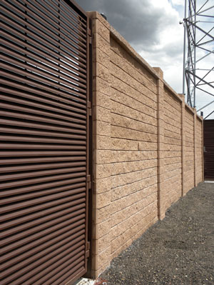
Modular Concrete Fence Systems
These specifications provide assistance to a broad range of professional concrete fence designers, allowing the designer to source and reference specific information for use in developing fence project documents. The goal is to provide formatted specification sheets that summarize information published by Allan Block and other relevant publications, as well as provide a comprehensive document for most applications which utilize mortarless concrete fence as the components to a block fence. The intent of these specifications are to assist the local fence design engineer, but not limit their flexibility for any given design situation.
Section 1
Part 1: General
1.1 Scope

Allan Block Fence
Work includes furnishing and installing modular concrete block fencing system to the heights and lengths specified on the construction drawings and as specified herein.
1.2 Reference Standards
ASTM C1372 Standard Specifications for Segmental Retaining Wall Units.
ACI 318: Chapter 5 – Mixing and Placing Concrete
1.3 Delivery Storage, and Handling
- Contractor shall check the materials upon delivery to assure proper material has been received.
- Contractor shall prevent excessive mud, concrete, and like construction materials from coming in contact with the materials.
- Contractor shall protect the materials from damage once on site. Damaged materials including cracked and chipped block beyond allowances provided for in ASTM C1372 must not be used in the fence.
Part 2: Materials
2.1 AB Fence Systems Units
- System units shall be AB Fence System units as produced by a licensed manufacturer.
- System units shall have a minimum 28 day compressive strength of 3000 psi (20.7 MPa) in accordance with ASTM C1372. The concrete units shall have adequat e freeze-thaw protection with an average absorpti on rat e of 7.5 lb/ft3 (120 kg/m3) for northern climates and 10 lb/ft3 (160 kg/m3) for southern climates.
- Exterior dimensions shall be uniform and consistent. Maximum dimensional deviations shall be 1/8 in. (3 mm), not including textured face
- Exterior shall be textured or striated or a combination of both. Color as specified by the project owner.
2.2 Pile and Post Concrete
- Concrete used to construct the piles and fill the post block must have a minimum compressive strength of 3000 psi (20.7 MPa).
2.3 Concrete Grout
- Concrete grout used as unit core fill for bond beam panel blocks shall conform to ASTM C476 and have a minimum compressive strength of 3000 psi (20.7 MPa) with Fine Aggregate Grading Requirements defined by ASTM C404.
2.4 Steel Reinforcement
- All reinforcing bars shall be deformed billet steel conforming to ASTM A615 grade 60. Bars shall be branded by the manufacturer with bar size and grade of steel, and certified mill reports shall be submitted for record.
2.5 Construction Adhesive
- Exterior grade construction adhesive used to adhere the cap block to both the posts and panels shall be NP1 as manufactured by BASF (or equivalent).
2.6 Shimming Material
- Material used for permanent shimming must be non-degradable.
Part 3: System Construction
3.1 Layout
- Excavate a 6 in. (150 mm) deep by 12 in. (300 mm) wide trench along the centerline of the AB Fence the entire length of the fence.
- To ensure accurate post spacing, installer shall follow all guidelines set for th in the Installation Manual for the AB Fence System.
- The center of each pile hole must be located and drilled to a maximum horizontal tolerance of ±1 in. (25 mm). The depth and diameter must be at least that specified in design.
- The top of the pile holes shall be set to a maximum of 1 in. (25 mm) below the design elevation of the pile. A 12 in. (300 mm) tall piece of cylindrical tubing material having a diameter of 24 in. (600 mm) is recommended to form up the top of the hole for setting the pile cap elevation.
3.2 Pile Construction
- Pour concrete into the pile hole meeting the strength requirements for the pile concrete and finish to a 1 in. (25 mm) maximum elevation difference.
- Place vertical steel reinforcement into the wet pile concrete within 0.5 in. (13 mm) of the design horizontal location for the steel. The steel bars must extend into the pile to the depth specified in the design with a minimum clear cover at the bottom of the pile of 3 in. (75 mm). The steel bars must also extend out the top of the pile a minimum distance to achieve a lap splice equal to the design requirements.
- Allow the concrete to harden 4 hrs at or above 40° F (4.4° C) or until hard enough to resist more than a surface scratch when scraped with steel rebar before placing post block.
3.3 Post and Panel Construction
- Fill trench between each post to the design elevation of the bottom of the fence with a well graded compactible aggregate to 95% Standard Proctor.
- If necessary, set the first post block on a mortar bed at a maximum thickness of 1 in. (25 mm) to accommodate for elevation differences. Post block must be placed level and plumb in all directions. Allow adequate curing time for the mortar before placing additional post block courses. Mortar strength must meet or exceed that of the design requirements of the post and pile.
- The panels must extend a minimum of 1 in. (25 mm) into the post block columns.
- Horizontal steel reinforcement must be installed in the specified bond beam locations. The horizontal steel must have a 1.5 in. (38 mm) clear cover at each end.
- The blocks should be installed level in all directions and in a straight line from post to post. Total deviation of 0.125 in. (3 mm) is allowable.
- The panel block must be stacked in a running bond or preset blended pattern.
- One panel block course above and below the horizontal steel in the bond beam locations must be filled with fine mix concrete grout meeting the strength requirements, and consolidation with a concrete vibrator. All panel block associated with a bond beam must cast in a single pour.
- Place 9 ga wire (min.) stirrups in each of the first two cores from each end and approximately every other core with one stirrup per block minimum.
- Minimum curing time for concrete grout is 4 hrs for the bottom bond beam and 2 hrs for all other locations.
- Maximum stacking lifts and filling for the post blocks is 4 ft (1.2 m) or 6 courses. Vertical steel reinforcement shall maintain a 1 in. (25 mm) clear cover from all inside surfaces of the post block. Minimum lap splice requirements are 24 in. (610 mm) or per design requirements and local building codes.
- Completed post must be installed level and plumb in all directions and within a ± ½° tolerance.
- Panels must be installed to a tolerance of 1 in. (25 mm) in the horizontal direction over the length of panel and a tolerance of 0.375 in. (8 mm) in the vertical direction.
Consult the Allan Block Engineering Department for additional details at engineering@allanblock.com or (800)899-5309. Specifications are subject to change without notice.

