Reinforced Retaining Wall Construction
Working with Geogrid
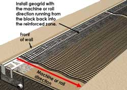
Install geogrid in the machine or roll direction
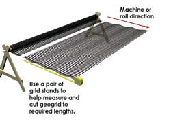
Reinforcement Grid
Geogrid typically comes in large rolls up to 13 ft (4 m) wide and 250 ft (76 m) in length. These “grids” also come in a variety of weights and strengths. Taller walls often require heavier strength grids, especially in the bottom portions of the wall. More information on types of geogrid.
It is critical that the correct grid is installed in the retaining wall. Check the engineered plans and specifications.
Most grids are strongest along the roll or machine direction. Reinforced grid designs require that all grids are placed with the machine direction running from the face of the wall towards the back of the excavation area.
See more information on using grid with corners and curves.
See the importance of reinforcement in your retaining wall with this sand castle demonstration.
How Grid Works
The sand castle test takes two cylinders of soil and applies vertical force to see how the soil performs. The first cylinder is just compacted material. The second is also compacted material with the addition of mesh screens to simulate the use of geogrid reinforcement. Learn more about how grid works...
For AB, AB Aztec, AB Metro & AB Europa Walls
Step 1: Site Prep and Excavation
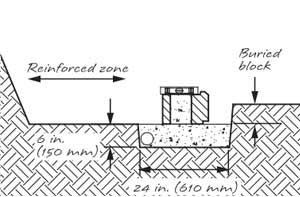
Reinforced retaining wall base course cross section
Foundation soils at the bottom of the base trench must be firm and solid. If the soils are made up of heavy clay or wet soils, or the areas have been previously excavated, remove entire material and replace with granular base, compacting in 8 in. (200 mm) lifts or less.
- Remove all surface vegetation and organic soils. This material should not be used as backfill.
- Excavate behind the wall to accommodate the design length of the geogrid. Refer to the approved plans for exact length.
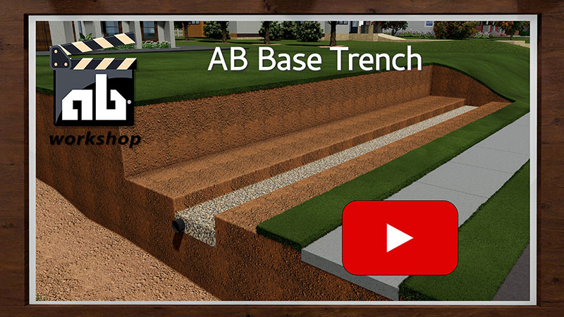
- Excavate base trench at the wall location. Dig the trench, per the approved plans, a minimum of 24 in. (610 mm) wide and 6 in. (150 mm) deep plus the required amount to accommodate the buried block.
- Buried block should be a minimum of 6 in. (150 mm) or 1 in. (25 mm) for each 1 ft. (300 mm) of wall height. See approved plans for exact amount needed.
- Compact and level base trench to 95% of Standard Proctor.
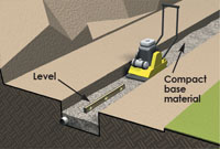
Install base material, level, and compact.
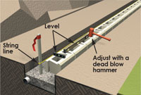
Install retaining wall base course
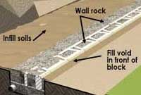
Install base course and wall rock
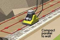
Compact wall rock and backfill soils
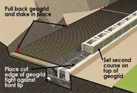
Install geogrid and stake into place
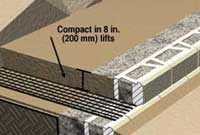
compact in 8in. (200 mm) lifts
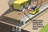
Keep heavy equipment away from the back of the block
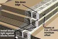
Install additional courses
Step 2: Install Base Material
The base material can be any compactible granular material. Allan Block recommends a well-graded aggregate, with a balanced mix of grain sizes, ranging from 0.25 in. to 1.5 in. (6 mm to 38 mm) diameter.
- Per the approved plans, place drain pipe at the back of the trench the length of the wall. The drain pipe will need to be vented to daylight or to a storm sewer system. See approved plans for location and specifications.
- Per the approved plan, place a minimum of 6 in. (150 mm) of base material in the base trench and rake smooth.
- Compact with a mechanical plate compactor
- Check the entire length for level, and adjust as needed.
Step 3: Install Base Course
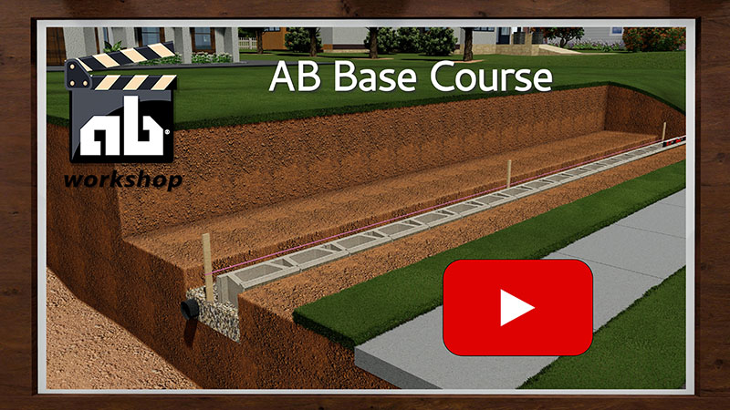
- Begin at the lowest wall elevation.
- Place all units top side up with the raised front lip facing up and in the center of the base material.
- Check and adjust for level and alignment of all wall blocks. Check block for level frequently from side-to-side and front-to-back. Verify the proper position of all AB units by examining a string line across the back of the blocks or by sighting down the back of the raised front lip.
- Make minor adjustments by tapping the AB units with a dead blow hammer or by placing up to 0.5 in. (13 mm) of coarse sand under the units.
- Irregularities in the base course become larger as the wall stacks up. Careful attention to a straight and level base course will ensure a quality finished wall.
Step 4: Install Wall Rock and Backfill Material
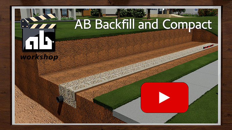
- Fill the hollow cores of the base course and 12 in. (300 mm) behind the block with wall rock. A compactible aggregate ranging in size from 0.25 in. to 1.5 in. (6 mm to 38 mm) in diameter, and containing less than 10% fines is recommended.
- Use approved infill soils to backfill behind the wall rock and in front of the base course.
Step 5: Compact
Compaction of the material behind the block is critical for a quality retaining wall.
- Use a mechanical plate compactor to consolidate the wall rock, then compact the backfill material immediately behind the block. Compact in a path parallel to the retaining wall, working from the back of the block to the back of the backfill material See additional details on compaction.
- Check the base course for level and adjust as necessary.
- All backfill soils must be compacted to a minimum 95% Standard Proctor. Use equipment appropriate for the soil being compacted.
- Remove all excess material from the top surface of all AB units. This prepares a smooth surface for placement of the next course. This can be assisted when installing the next course of block, by sliding the block into place.
- Every course after the first course requires compaction starting on the block.
Step 6: Install Geogrid
Refer to the plans for placement of grid; this example starts on the base course.
- Cut sections of geogrid to specified lengths. Check manufacturer’s grid specifications for strength, and roll or machine direction. Refer to the approved plans for exact size and location.
- Install the layer of geogrid by placing the cut edge to the back of the raised front lip and roll the layer out to the back of the excavation area. The excavation area must be fully compacted and level.
- Stack the next course of block on top of the geogrid, so that the blocks are offset from the blocks below. Each new course should be positioned so that the vertical seams are offset by at least 3 in. (75 mm) and are tight against the front edge of the units below. Perfect running bond is not required.
- Sight down the retaining wall line to check for a straight wall. Blocks may be adjusted slightly to form straight lines or smooth flowing curves.
- Pull on the back of the grid to remove any slack. Stake in place before installing wall rock and approved infill soils.
Step 7: Backfill and Compact
- Install wall rock in block cores and 12 in. (300 mm) behind wall. Use approved infill soils to backfill behind the wall rock in the reinforced zone.
- All wall rock and infill soils within 3 ft. (0.9 m) of the wall must be properly compacted using a mechanical plate compactor. Compact in maximum 8 inch lifts (200 mm), this time starting on the block and working in a path that runs parallel to the block towards the back of the reinforced zone. Compact all materials to a minimum 95% Standard Proctor.
- Never operate compaction equipment directly on geogrid.
- All heavy equipment must be kept at least 3 feet (0.9 m) from the back of the retaining wall. Wall designs typically do not account for surcharges from heavy compaction equipment. Even a properly installed and compacted retaining wall will rotate forward when extreme surcharges from heavy equipment are applied to the top of the retaining wall during construction and final grading.
- Check and adjust for level, alignment and the wall batter as the wall stacks up. It is acceptable to shim under blocks to compensate for a build up of tolerances or an out of level base condition. Asphalt shingles or geogrid work well when shims are required. The maximum allowable shim thickness per course is 1/8 in. (3 mm).
- Remove all excess wall rock and ridges or slag material from the top surface of all AB units. This prepares a smooth surface for placement of the next course. Plate compactors operated on top of the block will remove most slag material and prep the block for the next course. When installing the next course of block, sliding the block into place will also remove any slag material.
Step 8: Install Additional Courses
- Repeat steps 6 & 7 to complete retaining wall to height required, installing grid where needed per the approved plans.
- Use 8 in. (200 mm) of impermeable fill on the last lift to finish off wall.
- See more information on ending and topping off the retaining wall.
- For information on Allowable Construction Tolerances see the AB Spec Book
For AB Fieldstone Walls
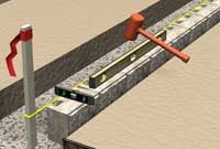
Install AB Fieldstone facing units. Level and Adjust
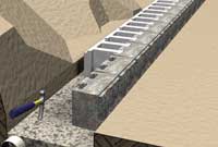
Install AB Fieldstone anchoring units
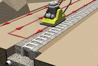
Compact wall rock and backfill soils
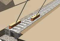
Sweep to remove excess materials for proper placement of the next course
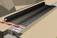
Install geogrid. Start in the middle of the facing unit and extend behind wall.
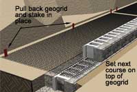
Stake geogrid in place. Install next course of block
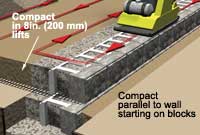
From the second course and up, compact starting on the wall and working to the back of the reinforced zone
Step 1: Install Base Course for AB Fieldstone
- Begin at the lowest wall elevation by placing the AB Fieldstone facing units on the base material towards the front of the trench, leaving room for the AB Fieldstone anchoring unit so when entire assembly is installed it is centered on the base materials. Install a string line at the back of the facing unit to ensure the proper positioning of all facing units.
- Adjust for level and alignment as each facing unit is installed.
- For proper placement of the AB Fieldstone anchoring units, use a brick hammer to create a small trench to allow for the lip.
- Install the anchoring units into the receiving slots of the facing units with the lip facing down in the trench just created. Make adjustments to ensure anchoring units are installed reasonably level with the facing unit. The anchoring units should never be installed higher than the facing unit. Except for special applications like corners, each anchoring unit should match up with one facing unit.
- A drain pipe is required for any reinforced wall, gravity walls over 4 ft. (1.2 m) tall or sites with poor drainage. Place the drain pipe at the lowest possible point toward the back of the trench and vent to daylight every 50 ft. (15 m). See approved plans for location and specifications. Learn more about water management.
Step 2: Install Wall Rock and Backfill Materials
- Fill the hollow cores and a minimum of 12 in. (300 mm) behind the wall with wall rock. Install the wall rock to be level or below the receiving notch of the anchoring unit. A compactible aggregate ranging in size from 0.25 in. to 1.5 in. (6 mm to 38 mm) in diameter, and containing less than 10% fines is recommended.
- Use approved soils to backfill behind the wall rock and in front of the base course.
Step 3: Compact
Compaction of the material behind the block is critical for a quality wall
- Use a mechanical plate compactor to consolidate the wall rock, then compact the backfill material immediately behind the block. Compact in a path parallel to the wall, working from the back of the block to the back of the backfill material See page 33 for additional details on compaction.
- Check the base course for level and adjust as necessary
- All backfill soils must be compacted to a minimum 95% Standard Proctor. Use equipment appropriate for the soil being compacted.
- Remove all excess material from the top surface of all AB units. This prepares a smooth surface for placement of the next course. This can be assisted when installing the next course of block, by sliding the block into place.
- Every course after the first course requires compaction starting on the block.
Step 4: Install Geogrid
- Cut sections of geogrid to specified lengths. Check manufacturer’s grid specifications for strength, and roll or machine direction. Refer to the approved plans for exact size and location.
- After the base course of blocks has been installed, roll out the geogrid reinforcement starting in the middle of the AB Fieldstone facing unit and extending back to the excavated area. The excavated area must be fully compacted and level.
- Stack the next course of block (facing and anchoring units) on top of the geogrid so the blocks are offset from the blocks below. Each new course should be positioned so the vertical seams are offset by at least 3 in. (75 mm) or 1/4 the length of the block. Perfect running bond is not required. The facing units can be randomly flipped upside down to give different facing appearances.
- Sight down the retaining wall line to check for a straight wall. Blocks may be adjusted slightly to form straight lines or smooth flowing curves.
- Pull on the back of the geogrid to remove any slack. Stake in place before installing wall rock and approved infill soils.
Step 5: Backfill & Compact
- Install wall rock in block cores and 12 in. (300 mm) behind wall. Use approved infill soils to backfill behind the wall rock in the reinforced zone.
- All wall rock and infill soils within 3 ft. (0.9 m) of the wall must be properly compacted using a mechanical plate compactor. Compact in maximum 8 inch lifts (200 mm), this time starting on the block and working in a path that runs parallel to the block towards the back of the reinforced zone. Compact all materials to a minimum 95% Standard Proctor.
- Never operate compaction equipment directly on geogrid.
- All heavy equipment must be kept at least 3 feet (0.9 m) from the back of the retaining wall. Wall designs typically do not account for surcharges from heavy compaction equipment. Even a properly installed and compacted wall will rotate forward when extreme surcharges from heavy equipment are applied to the top of the retaining wall during construction and final grading.
- Check and adjust for level, alignment and the wall batter as the wall stacks up. It is acceptable to shim under blocks to compensate for a build up of tolerances or an out of level base condition. Asphalt shingles or geogrid work well when shims are required. The maximum allowable shim thickness per course is 1/8 in. (3 mm).
- Remove all excess wall rock and ridges or slag material from the top surface of all AB units. This prepares a smooth surface for placement of the next course. Plate compactors operated on top of the block will remove most slag material and prep the block for the next course. When installing the next course of block, sliding the block into place will also remove any slag material.
Step 6: Install Additional Courses
- Repeat steps 3 & 4 to complete wall to height required, installing geogrid where needed per the approved plans.
- Use 8 in. (200 mm) of impermeable fill on the last lift to finish off wall.
- See more information on capping and on ending walls with turn-ins.

